


Power Systems - Let's Talk About Inverter Based Resources
Part 1

You have no doubt heard all the chatter about “IBRs” or Inverter Base Resources, they seem to be the buzz word of the day, but what are they? Well, they walk hand in hand with renewables.
Here is a list of renewable resources that use IBR’s and why.
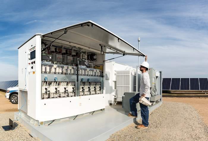
Solar Panel: The cells in these panels produce DC energy which is not compatible with our AC power system. The inverter coverts DC to AC to push out onto the Interconnection.
Wind Generators: These generators use permanent magnets for their magnetic field, and the speed they turn varies with the speed of the wind. The AC frequency they produce is not compatible with a synchronous parallel, so the output is rectified to DC then converted back to AC in an inverter. In the early days wind turbines used induction generators (overdriven induction motors) to generate power, but this caused multiple issues, and it was discontinued.
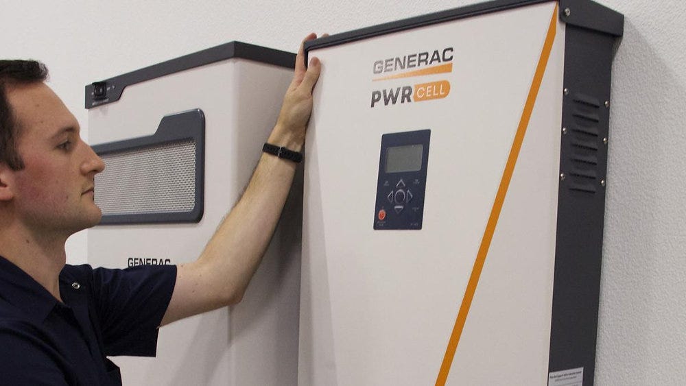
Batteries: It is well known that batteries use chemicals to produce DC power, an inverter is required to connect them to the Interconnection.
Other renewable energy like tidal energy, which is anything that cannot drive a prime mover at a constant synchronous speed, will be converted to DC then an Inverter will convert it to AC.
Inverters are also used in lots of places besides power generation, like variable frequency drives to control motor speeds, Uninterruptible Power Systems (UPS) that provide power critical systems like data centers and control rooms that cannot withstand a loss of power, medical equipment like the MRI machine, the wheel drive systems of EVs, the list goes on. So, they are everywhere.
On the power system we encounter three types of Inverters,
Grid Following Inverter (GFL): This style Power System of inverter makes up the vast majority of installations on the power system. They are simple, relatively inexpensive, and use the sine wave of the Interconnection they are connected to, to drive the inverter output waveform. This is the most prone inverter to disconnect during a system disturbance. Better inverters have more processing power and more sophisticated electronics, which is reflected in the price. Early models had no ride through capability, but newer models (often called smart inverters) should meet IEEE 1547-2018 that lists ride through requirements. It should be noted this is a voluntary standard and there is no aftermarket testing to verify compliance to manufacturers claiming to meet the standard.
Grid Forming Inverter (GFM): This style of inverter has the ability to generate a sine wave on its own with no grid reference. These are much more sophisticated and more expensive inverters. However, like the GFL inverters, there any many levels of sophistication (and price); from a simple home standby inverter, to an inverter providing synthetic inertia. The more complex the function, the more processing power required. GFM inverters are nearly always installed where there are batteries. For some grid forming functions to work properly they require a solid source of energy only a battery system will provide. This does not mean every battery system has a GFM inverter, but it would be rare to find a GFM inverter without batteries.
Hybrid: This type of inverter can be found where there is a solar panel array with batteries providing standby power. In normal operation the Inverter acts as a grid following inverter. However, when commercial power is lost, a contactor opens and the inverter switches to grid forming inverter function to keep the load energized until power returns or the batteries are depleted. These are mostly residential so they’re not terribly sophisticated inverters in that service.

This leads to the question, “why all the chatter”? Referring to my recent piece “The Iberian Blackout - On That Day”, the initiating cause appears to be the shutdown of renewable generation over a wide area. That type of shutdown is typical of an inverter trip, not the renewable generator itself, although they are very much connected at the hip. So what is causing this?
To answer that question we need to reach inside the grid following inverter logic a bit. (information below sourced from Google Gemini AI)
Modern GFL inverter logic generally works on a cascade control.
Outer Control Loop(s): These loops are responsible for controlling the macroscopic behavior of the IBR, often related to power exchange, voltage regulation, or frequency support. They operate at a slower time scale.
Power Control Loop: The most common outer loop for grid-following (GFL) inverters. It controls the active power (P) and reactive power (Q) injected into or absorbed from the grid. The outputs of these loops are usually current references (Id∗ and Iq∗) in the d-q rotating reference frame (where Id is related to reactive power/voltage and Iq to active power/torque, as discussed in Vector Control).
Frequency Control (Droop Control): For both GFL and GFM inverters, an outer frequency control loop (often implementing droop characteristics) adjusts the active power setpoint based on grid frequency deviations, providing frequency support.
Inner Current Control Loop (s): This is the faster, secondary loop that directly controls the inverter's output current. It operates at a much faster time scale, typically in the range of microseconds to milliseconds, and is almost universally implemented in the d-q rotating reference frame (vector control).
The current references (Id∗ and Iq∗) from the outer loops are fed into these inner loops.
These loops regulate the actual inverter currents (Id and Iq) to match their reference values.
The output of the inner current controllers (often PI controllers) are voltage commands (Vd∗ and Vq∗) which are then used by the PWM modulator to generate the switching signals for the power electronic switches.
A Phase-Locked Loop (PLL) is crucial here, providing the synchronization angle for the d-q transformation, ensuring that the current controllers operate in the correct rotating frame relative to the grid voltage.
Phase Lock Loop Logic appears to be at the core of what drives the operation of these GFL inverters, here is a description:
A PLL is a control system that generates an output signal whose phase is related to the phase of an input "reference" signal. In the context of IBRs, the PLL's primary function is to synchronize the inverter with the grid voltage. It achieves this by continuously tracking the phase angle and frequency of the grid.
A basic PLL typically consists of three main components:
Phase Detector (PD): Compares the phase of the input grid voltage signal with the phase of the output of the Voltage Controlled Oscillator (VCO). It produces an error signal proportional to the phase difference.
Loop Filter (LF): Filters the error signal from the phase detector, typically a low-pass filter, to smooth out high-frequency noise and to determine the dynamic response and stability of the PLL.
Voltage Controlled Oscillator (VCO): Generates an output signal whose frequency is proportional to the filtered error signal. This output frequency is adjusted until its phase matches the input grid voltage's phase.
When the PLL is "locked," the inverter's internal reference angle is perfectly synchronized with the grid voltage angle. This synchronized angle information is then used by the inverter's inner current control loops to inject active and reactive power into the grid.
Per IEEE 1547-2018 a modern inverter should provide the following ride through capabilities:
Low Voltage Ride-Through (LVRT): The ability to remain connected during temporary drops in grid voltage.
High Voltage Ride-Through (HVRT): The ability to remain connected during temporary increases in grid voltage.
Low Frequency Ride-Through (LFRT): The ability to remain connected during temporary drops in grid frequency.
High Frequency Ride-Through (HFRT): The ability to remain connected during temporary increases in grid frequency.
All in all, it’s a pretty complex control process requiring a fair bit of logic. Because things on the power system happen quickly the IBR has to be fast enough to keep up with the changes. If the processor falls behind or the PLL logic loses its sync lock the inverter will shut down on an internal safety. Some more advanced large grid following inverters having tuning capabilities that allow them to be adjusted or tuned to work with the power system that surrounds them. Properly tuned IBRs have much better chance of riding through a disturbance.
Before I move on, let’s talk about tuning as I mentioned in the paragraph above. This is where it gets pretty confusing when I am talking to the average person who has no PID controls experience. Just about every dynamic process that is controlled has a control loop. There is a difference between static controls and dynamic controls. A static control is an on/off like your thermostat, or the pressure switch for a well pump (unless it’s a constant pressure pump). Early loop controls started with Christiaan Huygens grist mill governor and progressed to the electronic controls of today. (reference Power Systems - Can't Vote for This Governor) I won’t dig too deep other than to say virtually all modern dynamic control loops contain at least one Proportional-Integral-Derivative (PID) control loop, and that every PID loop has tuning, some are factory set, some have self-tuning software, but the complex ones must be tuned to the environment in which they run. In the Distributive Control System World (DCS) there are very well-paid professionals whose primary job is to provide PID tuning for customers. For more information Wikipedia has an excellent article on PID loops including talking about tuning, you can read it HERE.
Let’s take a break and let all this sink in. We will pick up talking about grid forming inverters in Part 2. As always please comment and tell me your thoughts. See you in Part 2 …
Great article - thanks!
I'm continually amazed at how little I know (despite my batchlor's degree in physics, including courses on electricity and magnetism) and how much I'm learning just from following guys like you on substack.
Synchronous wind generators were originally touted as a source of employment since they require more maintenance than DC machines. Now someone realized that the cost savings from wind power will be reduced by labor cost, so we now need neodymium for permanent magnets in those machines.