


Power Systems - Can't Vote for This Governor

Governor, well we are certainly not talking about that slippery gentleperson in the office at the state capitol. If images come to mind of the Governor from the movie “Best Little Whorehouse in Texas”, you are on the wrong track. Still a great movie, you should rent it if you haven’t seen it. We are talking about machine speed governors, a whole different animal.
Chances are you have used a speed governor and don’t even know it. Cruise Control is a form of a speed governor. It controls the speed of your car, not the speed of your car’s engine. Think about next time you set your cruise control to 60 mph, then imagine you are actually setting it at 60Hz, then observe. You also most likely have a governor on your gas-powered lawn mower and/or snow blower

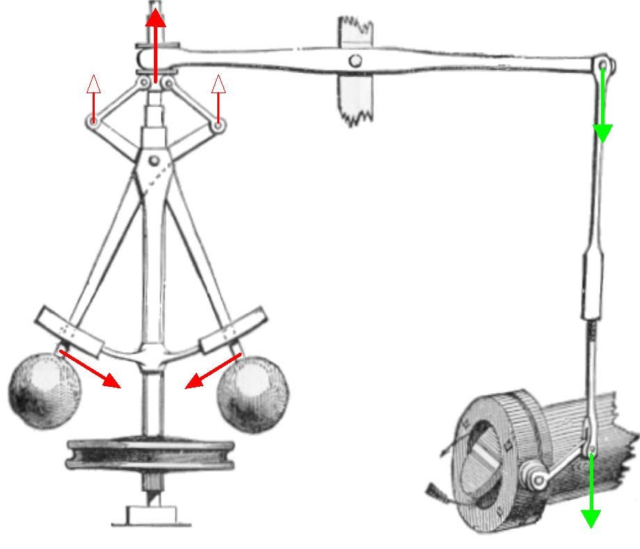
To understand how governors work, first let’s jump on the way back machine and go back to where they began. James Watt, the man who perfected the Newcomen steam engine by adapting a condenser and adding the ability to create rotary motion. It was necessary to develop a way to control the speed of the Watt Steam Engine as the load on the engine changed. Originally the flyball governor was invented by Christiaan Huygens to control windmill grinding stones (really hard to find information on). James Watt adapted that flyball governor (pictured below) to control his steam engine, the rest is history. This was the core basis for governors for the next 200 years. While the design was improved, the flyweight was used as the speed sensing element until the electronic age. It was even eventually retrofitted to the sluice gates on waterwheels.
.
So why are we talking about governors anyway? If you remember from our last session about frequency, turbine (prime mover) rpm directly affects the frequency output of synchronous generators. It is the combined electrical rpm of the grid that determines its frequency. While the control of an individual machine may seem like a non-issue, it is the combined control of all the synchronized machines that drives frequency, so they all matter. Now we will get into it later, but governors are no longer responsible for the fine frequency control on the system, having a working governor is very important.
We talked about what they are, and what they do, but we have not talked about how they work. We are going to talk about mechanical governors, believe it or not there are still a fair number of those out there. Now they are more complex than what we will discuss, but the basics are the same. In face even the electronic governors work on the same principles. A flyball governor works on the principle of gravity vs centrifugal force, or spring pressure vs centrifugal force on the newer models. The governor is rotated by a shaft and gear train, or by a belt that is driven by the main or an auxiliary shaft of the machine to be controlled. The speed of rotation will eventually cause the flyballs to move outward as speed increases. The outward movement of the flyballs moves linkage that reduces the “fuel” available to the prime mover. The “fuel flow and the flyball movement will reach a point of equilibrium presumably at the desired speed of the engine. A reduction in engine speed will increase “fuel”, an increase in engine speed will reduce “fuel”. Here are links to two videos showing flyball governors in action, one is short, one is long. The slang term “balls out” comes from the centrifugal ball governors. When the balls are fully out the engine, tactor, locomotive, is going as fast as the governor will allow.

Governors typically do not control prime mover speed exactly at the set point speed, this change in speed from no load to full load is called speed droop, or usually shortened to just droop. Now if you own a newish whole house standby generator, or your business has a large commercial standby generator, the chances are they have an electronic governor without any droop, known as an isochronous governor. Portables will have a mechanical droop governor. All governors connected to an Interconnection will have a specified droop setting on the governor. 5% is the most common, but not the only setting. To learn more about what droop settings are used in North America, see NERC Reliability Guideline - Primary Frequency Control, starting with page 11.

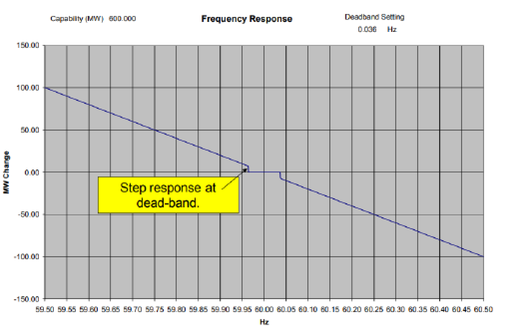
So why do we care about droop? Governor droop is how we get all the generators connected together across an Interconnection to share load. Let’s look at the 5% droop calculation. When you apply it to 60Hz, 60x.05= 3, you get a 3Hz change no load to full load on a generator. So, if you ran at 61.5Hz no load, you end up at 58.5Hz full load. You’re thinking “so, the grid runs at 60Hz”, and you would be correct. What droop does is catch the frequency when something goes wrong, and frequency starts to drop. As frequency declines, generators across the Interconnection increase their output with no external control. The same is true in the opposite direction if frequency suddenly rises, generators across the interconnection reduce output. The amount the governor changes generator output is proportional to the amount frequency changes. If you really want to calculate it here is the formula.
ΔP=Δf×P-rated/D
Where:
ΔP is the change in load
Δf is the change in frequency
P-rated is the rated power of the generator
D is the droop percentage (usually expressed as a fraction, e.g.5% droop would be 0.05)
NERC refers to this governor action as “Primary Frequency Control”.
So, does that mean governors are moving all the time? NO! Governors are also set with a dead band. Lots of things in your home have dead bands, like your thermostat, the temp control on your oven, even your cruise control. What the dead band consists of is “slop” built into the controls, so they are not continually taking action. It’s the temp band between where your air conditioning turns off and turns back on. On sophisticated thermostats like ecobee, you can go into the settings and tweak the dead band if you want. Generators connected to the Interconnection have a prescribed dead band setting, .036Hz is the most common. In that small dead band where the governors on the Interconnection are inactive, is where Automatic Generation Control (AGC) does the lion's share of the day-to-day work to control frequency. We will get into how AGC works later in another post. The NERC document NERC Reliability Guideline - Primary Frequency Control also lists governor deadband settings for the North American Interconnections.
This all sounds like everything works like clockwork, but hold on, let’s talk about some issues.
Boilers- It doesn’t matter what the fuel is, a swing in load on the boiler in either direction can trip the boiler. An increase in load will cause the drum level in the boiler to drop, and it takes a bit for the boiler controls to catch up. If the level drops too low, it will trip the boiler burners. If you unload the boiler, the drum level will swing high, too high and it will trip the turbine. So, the governor’s movement on steam turbines is deliberately slow to allow the boiler to keep up. These issues are compounded on solid fuel boilers where changes in fuel flow are slow. NOTE** Because a governor changing steam demand would swing steam demand, most nuclear plants have their governors blocked per NRC regulations. The NRC does not want to take any chances with swinging the reactor cooling flow.
Hydroelectric Turbines - These turbines fight with a phenomenon called water hammer. Attempting to change the rate of water flow through the penstock introduces water pressure stress on the penstock. It’s our old friend inertia at work. If you try to unload a hydro turbine too quickly you can rupture the penstock, just split it open. If you try to load a hydro generator too fast you can collapse the penstock, just like collapsing a straw in a milkshake. So hydro governors move deliberately slow to keep the penstock pressures in check.
Gas Turbines - On larger gas turbines, the compressor section runs on its own shaft, and the rpm of the compressor changes with load. Large gas turbines typically burn lean. A sudden drop in load can cause the compressor to snuff out the flame in the burner cans if fuel is reduced too quickly. This is called turbine blowout. If load increases too quickly before the compressor can catch up, the turbine will drop into temperature control or trip on high exhaust temp. Temperature control takes over fuel control to limit exhaust temp, all stationary gas turbines have it. Once again, the governor action is slowed to allow the compressor to catch up.
That just about covers governors, a long but very important topic. Next let’s get into inertia, why it’s important, and how it interacts with governor response on a frequency excursion.
So if you really want a governor all your own, here are a couple links
For a mechanical governor, you can still buy a belt driven Hoof Governor.
No place better than Governors of America for a wide selection of electronic governors and actuators.
Those self tuning PID controls are cool stuff. We had to hire a tuner for our DCS, but then that was the three element drum level control.
Thanks for the nice historical context of the mechanical governor. The discussion of different power sources, steam versus gas turbine vs hydroelectric penstock etc. and the reasons not to modulate power too quickly or too slowly was nicely done. This could have been a very dull and dry description, but you made it interesting. Overall, a governor is a feedback device. In electronics, we are always worried about oscillation with feedback devices, and at least one portion of the loop must have a substantially slower response than the prime mover to avoid oscillation. One can achieve oscillation if you meet the Nyquist criterion, and I will stop there as it is too mathematical to be interesting in a short comment.