


Power Systems - Let's Talk About Frequency

Hello, welcome back! Last time we talked about magnets, I am sure I left some of you scratching your heads as to why I would start there. Let’s start to pull things together here.
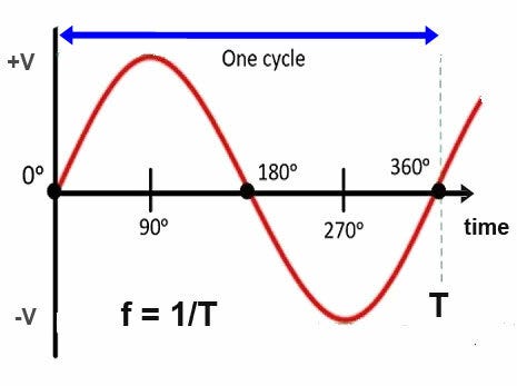
In this picture we have a sine wave, or by its full name a sinusoidal wave. This is one cycle. We measure the frequency of an electric power grid in cycles per second, or how many of the sine waves below occur in a second. We call this hertz (Hz). The North American power grids run at 60 cycles or 60Hz. Europe and much of Asia runs at 50Hz. Japan is half 60Hz and half 50Hz
.So, notice I said North American grids as in plural, not grid, as in singular. Yesterday I talked about Interconnections, notice I capitalized it. It is a NERC term, which is always capitalized. This is what the NERC Glossary of Terms says about Interconnections;
A geographic area in which the operation of Bulk Power System components is synchronized such that the failure of one or more of such components may adversely affect the ability of the operators of other components within the system to maintain Reliable Operation of the Facilities within their control. When capitalized, any one of the four major electric system networks in North America: Eastern, Western, ERCOT and Quebec.
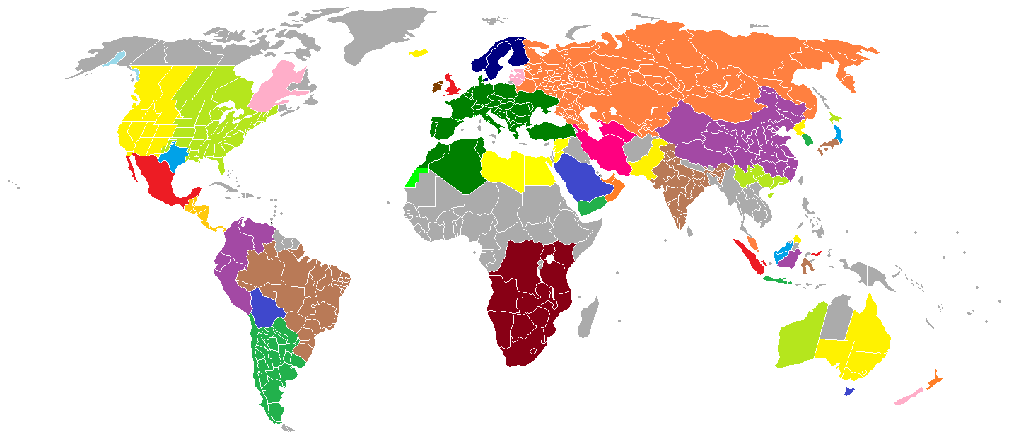
In “English” that means a network of electrical equipment connected via AC connections. A DC tie does not constitute a synchronous magnetic tie to the Interconnection. Boy that was a mouthful of word soup. But in reference to frequency, it means all the sine waves across the Interconnection are magnetically coupled, and the entire Interconnection runs at the same average frequency. I say average because the magnetic coupling has some flexibility, and there may be some momentary variances in frequency across the Interconnection as it flexes and stretches. Here is a map of the world Interconnections. Note their are still places that still do not have Interconnections like central Africa or other gray areas.
So, frequency is the heartbeat of an Interconnection, it is the only constant across the whole grid. Voltage will vary, current flow will vary, but for all practical purposes the frequency is the same everywhere. If you watch frequency, you have a pretty good idea when big things are going South.
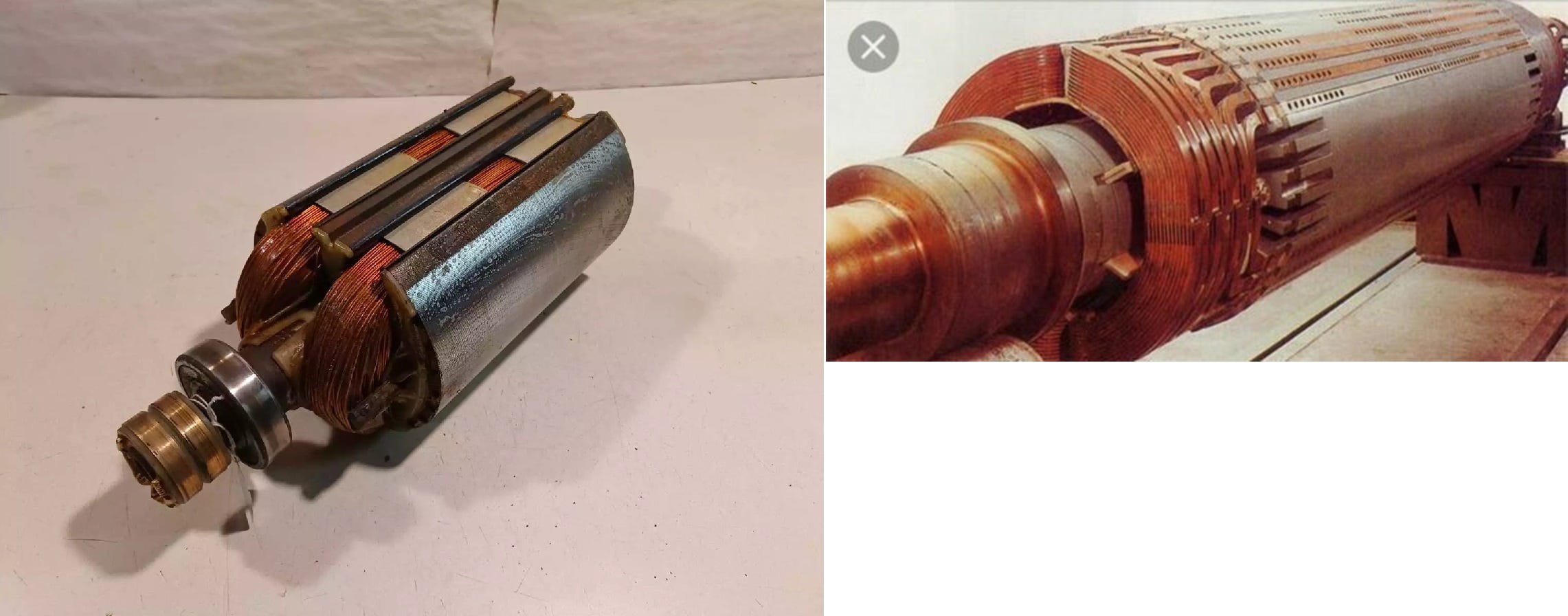
So back to fundamentals, what is the origin of a sine wave? Well, the generator of course, but that does not tell you much. Synchronous generators have a magnet that rotates inside coils of wire to make electricity, we have all heard that. That rotating magnet is called a rotor, and it’s more complex than that. The rotor has coils of wire called field windings wound around laminated steel called pole pieces. We run DC current through the coils to make the magnet field that rotates, we do not use permanent magnets. So, the number of pole pieces or poles is very important to frequency. If the rotor has two poles, there will be two poles wound into the stationary winding called the stator. The stator winding is also wound into laminated steel. The stator and the rotor must have the same number of poles.
But what does this have to do with frequency? Everything! As the rotor field passes by the stator winding it produces a sine wave. You can see it rise as it approaches, then fall as it departs, then rise the opposite direction as the poles switch positions. The number of cycles per second directly correlates to the revolutions per minute (rpm) of the rotor. A two-pole rotor rotating at 3600 rpm will produce 60Hz. The two-pole rotor must make a full revolution to make a cycle. A four-pole rotor must make a half revolution to make a cycle, a four-pole rotor turning 1800 rpm produces 60Hz. Warning, High School algebra in use!!!!. The formula for frequency output when poles and rpm are known is f=P×rpm/120, or where speed and frequency are known P=120×f/rpm. What this means is that there is mechanical speed of the device driving the generator, and there is electrical speed. The mechanical speed changes according to the number of poles in the generator, the electrical speed is always the same as the Interconnection.
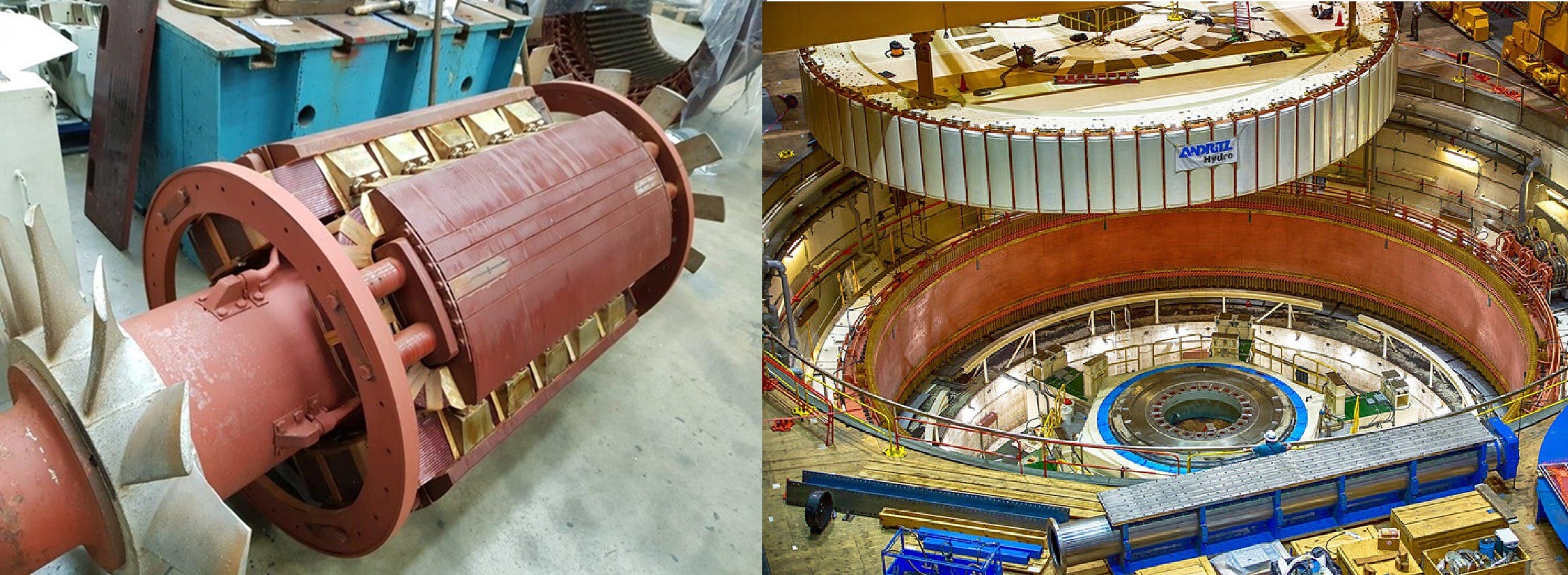
Here is a four pole rotor and a massive hydro rotor.
One final note before we close, we use electromagnets on the rotor so we can control the strength of the magnetic field. When we are disconnected from the Interconnection, changing the field strength directly changes the voltage output of the generator.
Next time let’s talk about governors, the mechanical ones, not the political ones, how they work, and why the matter to frequency. In the meantime, if you want to watch North American Frequency, follow this link.
You might mention that the huge rotor in the hydroelectric generation plant shown in the right frame of the final photographs has a very large number of poles because it rotates much slower than 3,600 RPM or 1,800 RPM. Large hydroelectric generators have significant amounts of synchronous grid inertia.